Analog-to-Digital Converter Reviewcopy link
Selecting an ADC for robotics applications with Raspberry Pi 4B
overviewcopy link
Robotics projects often require reading analog inputs, which is a capability not available on a Raspberry Pi. Adding inputs requires interfacing with an Analog-to-Digital Converter (ADC) and writing C++ code to read the channels.
This review will explore the commonly available options from Adafruit, Digikey, and Amazon and demonstrate the effort required to get them working.
mcp3008 adccopy link
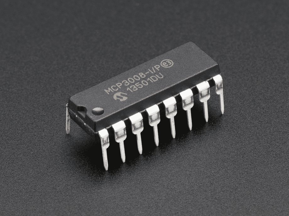
MCP3008 is an 8-channel, 10-bit ADC with 3.3V to 5V logic and a “4-wire” SPI interface, distributed by Adafruit. It’s simple to setup for a small project.
MCP3008 can be wired to the Raspberry Pi SPI0 bus as follows:
| MCP3008 | Rasberri Pi 4B | Description |
|---|---|---|
CLK | SCLK | SPI Clock |
DOUT | MISO | SPI Send |
DIN | MOSI | SPI Receive |
CS | Digital Pin 5 | SPI Select |
VDD | 3.3V | Power |
VREF | 3.3V | Power |
AGND | GND | Ground |
DGND | GND | Ground |
The inputs can be read using spiOpen and spiXfer from PiGPIO library:
#include <stdio.h>#include <pigpio.h>
// MCP3008 SPI rate (100 kbps)const int SPI_RATE = 100 * 1000;
// MCP3008 SPI modeconst int SPI_MODE = 0;
// MCP3008 channelsconst int CHANNELS = 8;
// Max value for a 10-bit sampleconst double MAX_VALUE = double(1 << 10);
// SPI bus handleint spi = -1;
/*  Initialize MCP3008 on Raspberry Pi 4B  initBus - The SPI bus to initialize on  returns true if successful, false otherwise*/bool init(int initBus){  if (gpioInitialise() < 0) return false;
  spi = spiOpen(initBus, SPI_RATE, SPI_MODE);
  if (spi < 0)  {    // Failed to open    return false;  }
  return true;}
/*  Read sample on a channel as an integer  channel - The channel to read  returns the sample converted from 10 bits to 32 bits*/int read(int channel){    char buffer[3] =    {      // Begin command      1,      // Select channel      char((8 + channel) << 4),      // End command      0    };
    spiXfer(spi, buffer, buffer, sizeof(buffer));
    return ((buffer[1] & 3) << 8) | buffer[2];}
/*  Entry point*/int main(){  // Initialize MCP3008 on SPI bus 0  if (!init(0)) return 1;
  // Read all channels  for (int channel = 0; channel < CHANNELS; channel++) {    int sample = read(channel);
    printf(      "channel %d: %d (%g)",      channel,      sample,      sample / MAX_VALUE    );  }
  return 0;}
It’s worth noting that the 16-channel analog input HAT for Raspberry Pi made by BC Robotics uses two MCP3008 chips thus you get the same quality with double the channels if you are OK with the HAT format.
ads1115 adccopy link
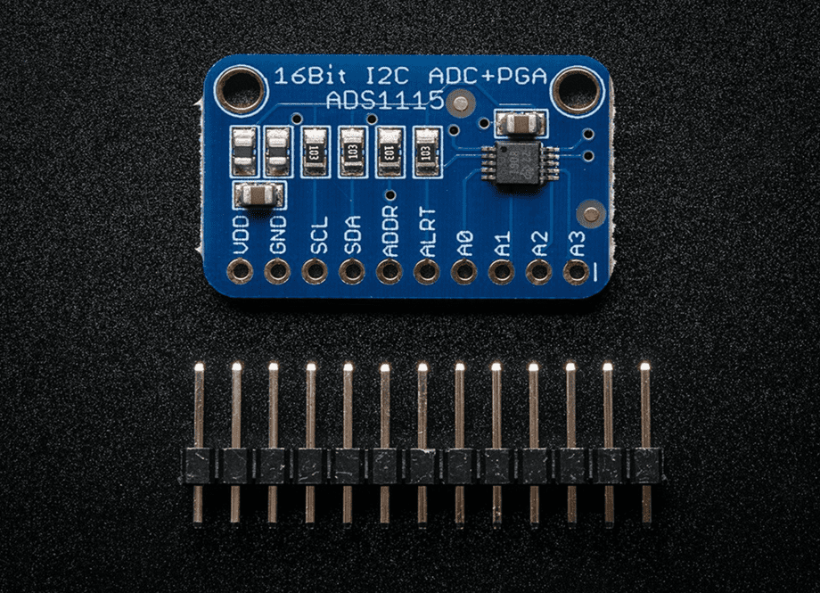
ADS1115 is a 4-channel 16-bit ADC with a “2-wire” I2C interface and 3.3V to 5V logic, distributed by Adafruit and Digikey.
It’s harder to use than MCP3008 and has less inputs, however it has a higher resolution and four ADS1115s can be chained together on a single I2C bus to read 16 analog inputs simultaneously at up to 860 samples per second.
/**/ This ADC has advanced features like a multiplexer and a comparator for reading the difference between pairs of inputs. The multiplexer reads samples from two pins and the comparator samples the difference.
ADS1115 can be wired to the Raspberry Pi I2C bus as follows:
| ADS1115 | Raspberry Pi 4B | Description |
|---|---|---|
SCL | SCL | I2C Clock |
SDA | SDA | I2C Data |
VDD | 3.3V | Power |
GND | GND | Ground |
Configuring ADS1115 involves writing a 16-bit value with various settings stored in bit-fields to its configuration register (encoded as two’s complement):
| Offset | Bits | Setting | Values |
|---|---|---|---|
0 | 2 | Alert Mode | 0 - Set ALERT after 1 conversion |
1 - Set ALERT after 2 conversions | |||
2 - Set ALERT after 4 conversions | |||
3 - Disable alerts (default) | |||
2 | 1 | Latch mode | 0 - ALERT does not latch |
1 - ALERT latches until read | |||
3 | 1 | Alert Polarity | 0 - ALERT is active low (default) |
1 - ALERT is active high | |||
4 | 1 | Comparator Mode | 0 - Traditional (default) |
1 - Window comparator | |||
5 | 3 | Sample Rate | 0 - 8 samples per second |
1 - 16 samples per second | |||
2 - 32 samples per second | |||
3 - 64 samples per second | |||
4 - 128 samples per second | |||
5 - 250 samples per second | |||
6 - 475 samples per second | |||
7 - 860 samples per second | |||
8 | 1 | Sample Mode | 0 - Continuous sampling |
1 - Single-shot sampling (default) | |||
9 | 3 | Gain | 0 - +/- 6.144V range |
1 - +/- 4.096V range | |||
2 - +/- 2.048V range (default) | |||
3 - +/- 1.024V range | |||
4 - +/- 0.512V range | |||
5 - +/-0.256V range | |||
12 | 3 | Multiplexer | 0 - Differential +AIN0, -AIN1 (default) |
1 - Differential +AIN0, -AIN3 | |||
2 - Differential +AIN1, -AIN3 | |||
3 - Differential +AIN2, -AIN3 | |||
4 - Single-ended +AIN0, -GND | |||
5 - Single-ended +AIN1, -GND | |||
6 - Single-ended +AIN2, -GND | |||
7 - Single-ended +AIN3, -GND | |||
15 | 1 | Command / Status | 0 - Noop (when writing), Conversion not ready (when reading) |
1 - Requesting conversion (when writing), Conversion ready (when reading) |
After the chip is configured, the analog inputs can be sampled by reading the conversion register. The process for reading a sample on a channel is:
- Write to the configuration register to request a conversion on a certain channel along with options like gain and sample rate
- Read the conversion status from the configuration register
- When the conversion status is ready, read the 16-bit sample from the conversion register and decode it from two’s complement
#include <stdio.h>#include <stdlib.h>#include <fcntl.h>#include <unistd.h>#include <sys/ioctl.h>#include <sys/types.h>#include <sys/stat.h>#include <inttypes.h>#include <linux/i2c-dev.h>#include <linux/i2c.h>
/*  Constants*/
// ADS1115 registersenum deviceRegister{    conversion    = 0b00,           // Conversion register    configuration = 0b01,           // Configuration register    loThreshold   = 0b10,           // Low Threshold register    hiThreshold   = 0b11            // High Threshold register};
// Configuration register bit 15 (1 bit long) meaning when readingenum readOperation{    busy          = 0b0 << 15,      // Conversion not ready    ready         = 0b1 << 15       // Conversion ready to read};
// Configuration register bit 15 (1 bit long) meaning when writingenum writeOperation{    noop          = 0b0 << 15,      // Not requesting anything    convert       = 0b1 << 15,      // Requesting conversion};
// Configuration register bits 12-14 (3 bits long)enum multiplexer{    diff_0_1      = 0b000 << 12,    // Select diff channel 0 to 1    diff_0_3      = 0b001 << 12,    // Select diff channel 0 to 3    diff_1_3      = 0b010 << 12,    // Select diff channel 1 to 3    diff_2_3      = 0b011 << 12,    // Select diff channel 2 to 3    single_0      = 0b100 << 12,    // Select channel 0    single_1      = 0b101 << 12,    // Select channel 1    single_2      = 0b110 << 12,    // Select channel 2    single_3      = 0b111 << 12     // Select channel 4};
// Configuration register bits 9-11 (3 bits long)enum gain{    pga_6_144V    = 0b000 << 9,     // +/-6.144V range    pga_4_096V    = 0b001 << 9,     // +/-4.096V range    pga_2_048V    = 0b010 << 9,     // +/-2.048V range*    pga_1_024V    = 0b011 << 9,     // +/-1.024V range    pga_0_512V    = 0b100 << 9,     // +/-0.512V range    pga_0_256V    = 0b101 << 9,     // +/-0.256V range    pga_0_256V2   = 0b110 << 9,     // not used    pga_0_256V3   = 0b111 << 9      // not used};
// Configuration register bit 8 (1 bit long)enum sampleMode{    continuous    = 0b0 << 8,       // Continuous conversion mode    single        = 0b1 << 8        // Power-down single-shot mode*};
// Configuration register bits 5-7 (3 bits long)enum sampleRate{    sps8          = 0b000 << 5,     // 8 samples per second    sps16         = 0b001 << 5,     // 16 samples per second    sps32         = 0b010 << 5,     // 32 samples per second    sps64         = 0b011 << 5,     // 64 samples per second    sps128        = 0b100 << 5,     // 128 samples per second*    sps250        = 0b101 << 5,     // 250 samples per second    sps475        = 0b110 << 5,     // 475 samples per second    sps860        = 0b111 << 5,     // 860 samples per second};
// Configuration register bit 4 (1 bit long)enum comparatorMode{    traditional   = 0b0 << 4,       // Traditional comparator*    window        = 0b1 << 4        // Window comparator};
// Configuration register bit 3 (1 bit long)enum alertPolarity{    activeLow     = 0b0 << 3,       // ALERT pin active low*    activeHigh    = 0b1 << 3        // ALERT pin active high};
// Configuration register bit 2 (1 bit long)enum latchMode{    nonLatching   = 0b0 << 2,       // ALERT does not latch    latching      = 0b1 << 2        // ALERT latches until read};
// Configuration register bits 0-1 (2 bits long)enum alertMode{    alert1        = 0b00 << 0,      // Set ALERT after 1 conversion    alert2        = 0b01 << 0,      // Set ALERT after 2 conversions    alert4        = 0b10 << 0,      // Set ALERT after 4 conversions    none          = 0b11 << 0       // Disable the comparator*};
// Max channels available on each ADS1115 deviceconst int CHANNELS = 4;
// How many times to retry polling for conversion resultconst int MAX_RETRY = 4;
// I2C addresses for multiple chained ADS1115 devicesconst uint8_t DEVICE_ADDRESS[] ={    0x48,                       // ADDR pin tied to GND*    0x49,                       // ADDR pin tied to VDD    0x4A,                       // ADDR pin tied to SDA    0x4B                        // ADDR pin tied to SCL};
// Shortcut to select a channel to read fromconst uint16_t SELECT_CHANNEL[] ={    multiplexer::single_0,      // Select channel 0    multiplexer::single_1,      // Select channel 1    multiplexer::single_2,      // Select channel 2    multiplexer::single_3       // Select channel 3};
// Shortcut to look up delay for sample rateconst int DELAYS[] ={    1000 + 1000 * 1000 / 8,     // Delay for 8 samples/sec rate    1000 + 1000 * 1000 / 16,    // Delay for 16 samples/sec rate    1000 + 1000 * 1000 / 32,    // Delay for 32 samples/sec rate    1000 + 1000 * 1000 / 64,    // Delay for 64 samples/sec rate    1000 + 1000 * 1000 / 128,   // Delay for 128 samples/sec rate    1000 + 1000 * 1000 / 250,   // Delay for 250 samples/sec rate    1000 + 1000 * 1000 / 475,   // Delay for 475 samples/sec rate    1000 + 1000 * 1000 / 860    // Delay for 860 samples/sec rate};
/*  State*/
// I2C bus on which ADS1115 device(s) are attachedint i2cBus = 0;
// Number of chained ADS1115 devicesint devices = 0;
// Gain modegain gain;
// Sample ratesampleRate rate;
// I2C device handleint i2c = -1;
/*  Operations*/
/*  Initialize ADS1115 on Raspberry Pi 4B  initGain - The gain to configure  initRate - The sample rate to configure  initDevices - How many ADS1115 are chained on I2C bus  initBus - Which I2C bus to use  returns true if successful, false if failed*/bool init(  gain initGain,  sampleRate initRate,  int initDevices,  int initBus) {  // Open I2C bus  char busName[16] = {0};  sprintf(busName, "/dev/i2c-%d", initBus);  i2c = open(busName, O_RDWR);
  // Failed to open I2C bus  if (i2c < 0) return false;
  // Initialize state  i2cBus = initBus;  devices = initDevices;  gain = initGain;  rate = initRate;
  return true;}
/*  Helper method to request conversion on a channel  device - The index of ADS1115 to talk to (up to 4 can be chained)  channel - The channel to read  config - The configuration options*/void configure(int device, int channel, uint16_t config) {  // Select device to talk to on I2C bus  if (i2c < 0 || ioctl(i2c, I2C_SLAVE, DEVICE_ADDRESS[device]) < 0)  {    // Failed to select device    return false;  }
  // Include a command to switch channel  config |= SELECT_CHANNEL[channel];
  // Encode command to write to configuration register  uint8_t command[] = {    // Select configuration register    deviceRegister::configuration,    // Configuration register value MSB (two's complement)    ((uint8_t*)&config)[1],    // Configuration register value LSB (two's complement)    ((uint8_t*)&config)[0]  };
  if (write(i2c, command, sizeof(command)) != sizeof(command))  {    // If size to write != size written, error    return false;  }
  return true;}
/*  Helper method to wait for conversion result  channel - The channel to poll  returns true if ready to read, false otherwise*/bool poll(int channel) {  uint8_t buffer[2] = {0};  uint16_t config = 0;  int retries = 0;
  do  {    // Wait for configuration to take effect    usleep(DELAYS[rate >> 5]);
    // Read configuration register    if (read(i2c, &buffer, sizeof(buffer)) != sizeof(buffer))    {      // Failed to read      return false;    }
    // Decode configuration register value from two's complement    config = buffer[0] << 8 | buffer[1];  }  while  (    // Wait until conversion is ready...    config & readOperation::ready == 0 &&    // for this channel...    ((config >> 12) & 0b111) != (SELECT_CHANNEL[channel] >> 12) &&    // and there are retries left    retries++ < MAX_RETRY  );
  return retries < MAX_RETRY;}
/*  Helper method to read conversion result when ready  value - The variable to set to the conversion result  returns true if read successfully, false otherwise*/bool readConversion(uint16t& value) {  // Select conversion register  uint8_t command[] = { deviceRegister::conversion };
  if (write(i2c, command, sizeof(command)) != sizeof(command))  {    // Size to write != size written, failed to write    return false;  }
  // Read conversion register  uint8_t conversion[2] = {0};
  if (read(i2c, &conversion, sizeof(conversion))      != sizeof(conversion))  {    // Size to read != size read, failed to read    return false;  }
  // Decode conversion from two's complement  value = conversion[0] << 8 | conversion[1];  return true;}
/*  Sample a channel on a device  device - The index of ADS1115 if multiple, or 0  channel - The channel on ADS1115 0-3  sample - The value sampled  returns true if sampled successfully, false otherwise*/bool read(int device, int channel, uint16t& sample) {  uint16_t config =    // Command to request conversion    writeOperation::convert |    // Set gain    gain |    // Set single-shot conversion mode    sampleMode::single |    // Set sampling rate    rate |    // Not using comparator    comparatorMode::traditional |    // Not using latching    latchMode::nonLatching |    // Not using alerts    alertMode::none |    alertPolarity::activeLow;    if (configureDevice(device, channel, config) &&      pollDevice(channel) &&      readConversion(sample))  {    return true;  }
  return false;}
/*  Entry point*/
int main(){  // Initialize one ADS1115 on I2C bus 0 with default gain & rate  if (!init(gain::pga_2_048V, sampleRate::sps128, 1, 0))    return 1;
  // Read all channels  uint16t sample;
  for (int device = 0; device < devices; device++)  {    for (int channel = 0; channel < CHANNELS; channel++)    {      if (read(device, channel, sample)) {        printf(          "device %d channel %d = %d\n",          device,          channel,          sample        );      }    }  }
return 0;}pi-16adc hatcopy link
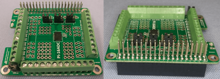
Pi-16ADC is a 16-bit, 16 channel ADC with 3.3V logic, designed for use as a HAT for the Raspberry Pi and sold on Amazon. It’s simple but slow (10 seconds to read all 16 inputs) and it takes up all the pins on the Pi even though it only uses I2C0, 3.3V, and GND.
Analog inputs can be connected via large screw terminals or soldered in, which makes Pi-16ADC attractive for prototyping. There is no wiring diagram because it automatically connects itself to the I2C bus when installed.
Once installed, the ADC should appear on the I2C bus at address 0x76 as can be verified by running i2cdetect in a terminal. Another address can be picked by setting A0, A1 and A2 jumpers.
Successive reads must be enabled for I2C to use this device:
# enable successive reads on I2C bus in Raspbianecho -n 1 > /sys/module/i2c_bcm2708/parameters/combinedSamples can be read on the Raspberry Pi as follows:
#include <stdio.h>#include <stdlib.h>#include <fcntl.h>#include <unistd.h>#include <string.h>#include <sys/ioctl.h>#include <sys/types.h>#include <sys/stat.h>#include <linux/i2c-dev.h>#include <linux/i2c.h>
// Pi-16ADC addressconst int DEVICE_ADDRESS = 0x76;
// Number of channelsconst int CHANNELS = 16;
// Max sample valueconst int MAX_VALUE = 0x800000;
// Max retries to acquire a sampleconst int MAX_RETRY = 8;
// How long it takes  to read a channelconst int DEFAULT_DELAY_US = 200 * 1000;
// Reset commandconst uint16_t RESET_COMMAND = 0xA0;
// Channel switching commandsconst uint8_t CHANNEL_COMMANDS[] ={           // PREAMBLE SGL CHANNEL    0xB0,   // 101      1   0000    0xB8,   // 101      1   1000    0xB1,   // 101      1   0001    0xB9,   // 101      1   1001    0xB2,   // 101      1   0010    0xBA,   // 101      1   1010    0xB3,   // 101      1   0011    0xBB,   // 101      1   1011    0xB4,   // 101      1   0100    0xBC,   // 101      1   1100    0xB5,   // 101      1   0101    0xBD,   // 101      1   1101    0xB6,   // 101      1   0110    0xBE,   // 101      1   1110    0xB7,   // 101      1   0111    0xBF    // 101      1   1111};
// I2C bus handleint i2c = -1;
/*  Initialize Pi-16ADC on Raspberry Pi 4B  initBus - the I2C bus to initialize on  returns true if initialized successfully, false otherwise*/bool init(int initBus){  char busName[16] = {0};  sprintf(busName, "/dev/i2c-%d", initBus);
  i2c = open(busName, O_RDWR);  if (i2c < 0) return false;
  if (ioctl(i2c, I2C_SLAVE, DEVICE_ADDRESS) == -1)    return false;
  if (!configure(RESET_COMMAND)) return false;
  return true;}
/*  Send I2C command to configure the ADC  config - The configuration to set  returns true if configured successfully, false otherwise*/bool configure(uint8_t config){  int result = 0;
  for (int attempt = 0; attempt < MAX_RETRY; attempt++)  {    result = write(i2c, &config, 1);    usleep(DEFAULT_DELAY_US);
    if (result == 1) break;  }
  if (result != 1) return false;
  return true;}
/*  Read a conversion from a channel  channel - The channel to read (0 through 16)  value - The value to read  returns true if read successfully, false otherwise*/bool read(int channel, int& value) {  // Switch channel and wait  if (!configure(CHANNEL_COMMANDS[channel]))    return false;
  // Read conversion  unsigned char buffer[3] = {0};  if (read(i2c, buffer, sizeof(buffer)) != sizeof(buffer))    return false;
  // Return max value when floating (nothing connected)  if ((buffer[0] & 0b11000000) == 0b11000000)  {    value = MAX_VALUE;    return true;  }
  // Decode conversion  value =    ((buffer[0] & 0x3F) << 16) +    (buffer[1] << 8) +    (buffer[2] & 0xE0);
  return true;}
int main(){  int value;
  if (!init(0)) return 1;
  for (int n = 0; n < CHANNELS; n++)  {    if (read(value)) printf(      "channel %d: %d\n", channel, value    );  }
return 0;}arduino microcopy link
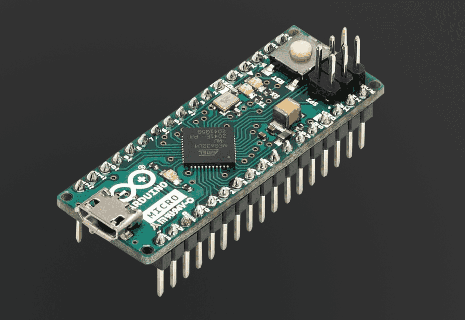
Attaching an Arduino Micro to the Raspberry Pi to read 12 analog inputs at 10bit resolution is a great option because it lets you design and test your own programming interface for sampling inputs.
Receiving data from an Arduino via a USB serial port in C++ is simpler than using a complex ADC chip that tries to be everything for everyone.
The following samples all analog pins on the Arduino and continuously sends the samples over the serial port in a binary (28-byte) payload:
// Arduino Micro analog channelsconst int CHANNELS = 12;
// Signature for each data frameconst unsigned char SIGNATURE[] = { 'a', 'd', 'c', 'd' };
// Pins on Arduino Micro that correspond to each channelconst int PINS[] ={  A0,   // Analog 0  A1,   // Analog 1  A2,   // Analog 2    A3,   // Analog 3  A4,   // Analog 4  A5,   // Analog 5
  A6,   // Digital 4  A7,   // Digital 6  A8,   // Digital 8
  A9,   // Digital 9  A10,  // Digital 10  A11,  // Digital 12};
// Data transfer structure to send values of all channelsstruct SAMPLE{  unsigned char signature[4];  short readings[sizeof(CHANNELS)];};
struct SAMPLE sample;
void setup(){  Serial.begin(9600);
  for (int channel = 0; channel < CHANNELS; channel++)    pinMode(PINS[channel], INPUT);    memcpy(&sample.signature, SIGNATURE, sizeof(SIGNATURE));}
void loop(){  for (int channel = 0; channel < CHANNELS; channel++)  {    sample.readings[channel] = analogRead(PINS[channel]);  }
  Serial.write((unsigned char*)&sample, sizeof(sample));
  // This can be as fast as the Arduino  delay(500);}
Attaching an Arduino to Raspberry Pi via USB will make it appear as one of the available devices under /dev/ttyACM* or /dev/ttyUSB*:
ls /dev/tty*The following listing reads the samples from the serial port on the Raspberry Pi with the PiGPIO library assuming Arduino is detected on /dev/ttyACM0:
#include <stdio.h>#include <pigpio.h>
// Arduino Micro analog channelsconst int CHANNELS = 12;
// Signature for each data frameconst unsigned char SIGNATURE[] = { 'a', 'd', 'c', 'd' };
// Data transfer structure to send values of all channelsstruct SAMPLE{  unsigned char signature[4];  short readings[CHANNELS];};
// Serial bus handleint usb = -1;
/*  Initialize serial connection from Raspberry Pi to Arduino Micro  busName - The bus name like /dev/tty* or /dev/serial*  returns true if successful or false otherwise*/bool init(const char* busName){  // Initialize pigpio  if (gpioInitialise() < 0) return false;
  // Open serial bus  usb = serOpen(busName, 9600, 0);
  if (usb < 0)  {    // Failed to open    return false;  }
  return true;}
/*  Read samples from Arduino Micro  readingCount - How many samples to read  readings - the buffer that receives samples  return true if successful or false otherwise*/bool read(int readingCount, int* readings){  SAMPLE sample;
  if (serDataAvailable(usb) < sizeof(SAMPLE))  {    // Not enough data to read    return false;  }
  if (serRead(usb, (char*)&sample, sizeof(SAMPLE)) != sizeof(SAMPLE))  {    // Failed to read    return false;  }
  if (memcmp(sample.signature, SIGNATURE, sizeof(SIGNATURE)) != 0)  {    // Invalid or corrupted data    return false;  }
  for (int n = 0; n < readingCount; n++)  {    readings[n] = sample.readings[n];  }
  return true;}
/*  Entry point*/int main(){  // Initialize Arduino Micro on ttyACM0  init("/dev/ttyACM0");
  // Read samples  while (true)  {    int readings[CHANNELS] = {0};
    if (read(CHANNELS, readings))    {      for (int n = 0; n < CHANNELS; n++)      {        printf("channel %d: %d\n", readings[n]);      }    }  }
  return 0;}
To give any of the executables built from samples in this article the ability to access various ports such as I2C, SPI, or USB you may have to give it root permissions (for example as part of the build process):
sudo chown root:root filenamesudo chmod +s filename


